The GEC4 Demo (Part 3)
  while ( true )
  do
    ./fltr --cmd update_result --fpid 0 --fid 6 --txdaddr 10.1.32.2 --txdport 20000 --qid 12 --sindx 49
        sleep 10
    ./fltr --cmd update_result --fpid 0 --fid 6 --txdaddr 10.1.16.2 --txdport 20000 --qid  9 --sindx  6
        sleep 10
  done
In the last part of the experiment, we demonstrate the effect of installing a filter that sends traffic from H1 to H4 via R3-R2 rather than directly through R2 and then restoring the filter that uses the original route directly through R2. The script change1Filter.sh is shown above. It repeatedly modifies (--cmd update_result) filter 6 (--fid 6) so that the destination queue and destination socket cause the packets from H1 to H4 to go through R3 for 10 seconds and then R2 for 10 seconds before repeating the same sequence.
We run this experiment in the same manner that we ran the one in Part 2 (The GEC4 Demo (Part 2)):
- Start the three receivers on onl038, onl039 and onl040 by running the script start_recvs.sh on onl035.
- Start the three traffic generators on onl035, onl036 and onl037 by running the script start_xmits.sh 1200 120000 200 on onl035.
- Run the change1Filter.sh script on R1's GPE.
As in Part 2, the arguments to the start_xmits.sh script will send 1200-byte UDP packets at a rate of 120,000 Kb/s (i.e., 120 Mb/s) for 200 seconds. The 200 seconds allows you to start the change1Filter.sh script and observe the effect of forwarding H1-H4 traffic directly through R2 and circuitously through R3 then R2 from R1.
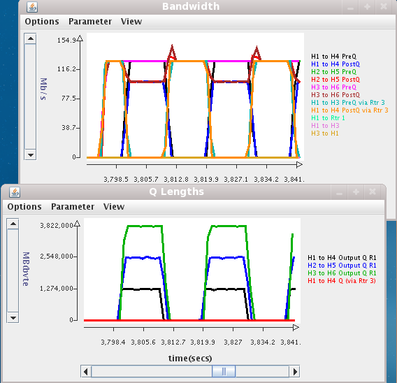
The effect of installing the filter is shown in the two charts in the figure (right). When the new filter is installed, the Bandwidth (top) chart shows traffic now flowing in the plot labeled H1 to H4 PostQ via Rtr 3 (orange line) instead of the ones labeled without the words via Rtr 3. This behavior lasts for 10 seconds until the filter switches the H1-H4 traffic back to the direct route through R2. Then, the pattern repeats again after another 10 seconds.
Also, there is no backlog in queue 12 (H1 to H4 output Q (via Rtr3)) when the traffic is routed through R3 because the packets go out R1 on meta-interface 5 which has a capacity of 300 Mb/s, and the meta-interface on R3 going to R2 also has a capacity of 300 Mb/s. There is only a backlog in queue 9 (H1 to H4 Output Q R1) when the original filter is reinstalled to send H1-H4 traffic directly to R2. If you look at both charts, when the orange line (H1 to H4 PostQ via Rtr 3) in the top chart shows no traffic the bottom chart shows that there is queueing because all traffic including the H1-H4 traffic is flowing through the bottleneck port.
