Dev:Forest - an overlay network for distributed applications
This page describes the high level architecture for the scalable network game system, focusing on the major system components, their interfaces and functionality. We envision several different implementations of the architecture, for different deployment contexts. These contexts include the Open Network Lab, the Supercharged PlanetLab Platform, Vini and Amazon EC2. Some of these (perhaps all) will be incomplete, but we want to maintain a reasonable degree of consistency across the platforms to minimize the amount of redundant work that will be required.
Contents
Major Components
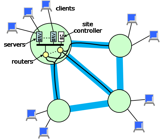
The network game system is distributed across multiple site. Each site has a known geographic location and includes a multiplicity of processing resources of various types. In particular, each site has one or more servers and routers. Servers connect to remote users or clients over the Internet and communicate with other servers through the routers. Sites are connected by metalinks which have an associated provisioned bandwidth. Multiple routers at a site may share the use of a metalink going to another site, but must coordinate their data transmissions so as not to exceed its capacity. In addition, each site has a site controller which manages the site and configures the various other components as needed. These ideas are illustrated in the figure below. In the planned SPP deployment, each site will correspond to a slice on an SPP node (including a fastpath for the routing function and a GPE portion that implements the site controller functions), plus a set of remote servers which will be connected to the SPP node over statically configured tunnels.
In addition to the components shown in the diagram, there is a web site through which clients can register, learn about game sessions in progress and either join an existing session or start a new one. When the user requests to join a session, the system will select a server and return its IP address and a session id to the client, who will use these to establish a connection to the server and join the session.
Common Packet Format
The various system components communicate by sending packets of various types. Here we describe the fields that are common to all packets and the basic packet format. Specific protocols used by the various components define additional fields. The description of these fields and formats is given in the specific sections dealing with the components that define the protocols.
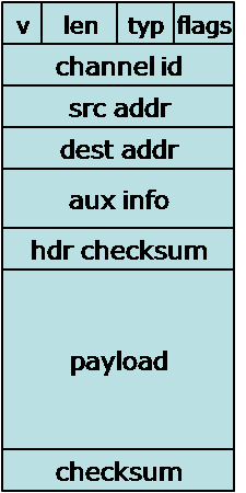
The common packet format is shown at right and the fields are described below.
- Version (4 bits). This field defines the version of the protocol suite. The current version is 1.
- Length (12 bits). Specifies the number of bytes in the packet. Must be divisble by 4 and can be no larger than 1400.
- Protocol (4 bits). This field defines the protocol that the packet is associated with.
The currently defined protocols are
- 0 - Session Control and Operation.
- 1 - Network Status
- Type (12 bits). This field defines the type of the particular packet. Each protocol defines its own set of types.
- Source Address (32 bits). This specifies the address of the component that sent the packet.
- Destination Address (32 bits). This specifies the address of the component to which the packet is being sent.
- CRC (32 bits). Error check computed over the entire packet.
Naming and Addressing
Every component in the system has a unique human-readable name. Names are text strings made up of the usual alphanumeric characters, and may have a maximum of 100 characters. Named components include sites, servers, routers, clients and site controllers. By convention, server names take the form "siteName/sXXX" where "XXX" represents a decimal value with up to 10 digits. Similarly, router names take the form "siteName/rXXX" and site controller names take the form "siteName/cXXX".
System components also have addresses which serve as concise machine-readable identifiers and provide location information. The first 16 bits of each 48 bit address identifies a site, and the remaining 32 bits identify a component associated with that site. The site component of the address is called the site id and the remainder is called the component number. Components with addresses includes servers and routers, but also clients who are currently connected to some game session through the site. Clients are assigned an address as part of the login process through which they connect to a site. All packets sent by the client through their access connection must include their assigned source address. Packets that don't contain the proper source address will be ignored. Note that each client will also typically have an IP address which is used for communication across the Internet to the access site through which it participates in game sessions. These addresses are only used access communication.
By convention, the system components at a site have component numbers between 1 and <math>2^{24} -1</math>. Addresses for clients have component numbers <math>2^{24}</math> and above. Component number 0 is used for context-dependent addressing. Packets addressed in this way are delivered to some entity within the specified site; which entity is typically determined by the type of the packet and possibly some other packet-specific context information. Similarly, site number 0 is used for context-dependent addressing. These values may not be used in the source address field of a packet.
System Data
This section summarizes the major system level data structures. The first three items below (client data, connection data and session data) are stored in a distributed hash table, with each site responsible for a portion of the key space in the DHT. The key space covered by each site is known by the other sites, allowing one-hop access to data in the DHT.
Client data
- User name (key)
- User preferences
- Accounting records
- Current connection(s)
Client connection data
- Associated user
- Access connection details (client IP address, access site, access site IP address and port)
- Address in the game network (key)
- Current session(s)
Session data
- Session id (key)
- Users in the session (specified in terms of client addresses)
- Multicast tree - sites, inter-site links with reserved capacities
The network status information logically forms a graph, with data associated with its nodes and links. Each site maintains the authoritative information about itself and its incoming links, but each site also maintains a complete copy of the global network status. The status information is distributed across a multicast spanning tree of the network, with each node periodically sending a copy of its current status on the multicast tree. The construction of the multicast spanning tree is carried out by a distributed spanning tree maintenance algorithm.
Network Status
- List of sites with up/down status, provisioned capacity (in terms of client sessions) and available capacity.
- Inter-site links with up/down status, provisioned capacity and available capacity.
State Update Distribution
Region Subscription
User Connection and Startup
Session Creation
Network State Management
Include neighbor discovery, topology maintenance, etc.
Multicast Tree Routing
foo

