Difference between revisions of "Internet Scale Overlay Hosting"
Jon Turner (talk | contribs) |
Jon Turner (talk | contribs) |
||
| Line 243: | Line 243: | ||
=== Control Software === | === Control Software === | ||
| − | [[Image:ctlsw.png|right| | + | [[Image:ctlsw.png|right|250px|Control Software]] |
== Planned SPP Deployment == | == Planned SPP Deployment == | ||
Revision as of 14:30, 19 March 2009
Network overlays have become a popular tool for implementing Internet applications. While content-delivery networks provide the most prominent example of the commercial application of overlays, systems researchers have developed a variety of experimental overlay applications, demonstrating that the overlay approach can be an effective method for deploying a broad range of innovative systems. An Overlay hosting Service (OHS) is a shared infrastructure that supports multiple overlay networks and can play an important role in enabling wider-scale use of overlays, since it enables small organizations to deploy new overlay services on a global scale without the burden of having to acquire and manage their own physical infrastructure. Currently, PlanetLab is the canonical example of an overlay hosting service, and it has proven to be an effective vehicle for supporting research in distributed systems and applications. This project seeks to make PlanetLab and systems like it more capable of supporting large-scale deployments of overlay services, through the creation of more capable platforms and the control mechanisms needed to provision resources for use by different applications.
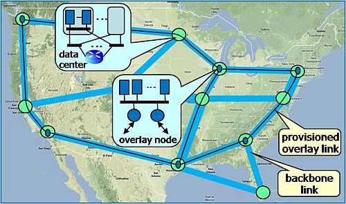
As shown at right, an OHS can be implemented using distributed data centers, comprising servers and a communications substrate that includes both L2 switching for local communication and L3 routers for communication to end users and other data centers. End users communicate with a data center using the public Internet, while data centers can communicate with each other, using either the public Internet or dedicated backbone links, allowing the OHS to support provisioned overlay links. This in turn allows overlay network providers to deliver services that require consistent performance from the networking substrate.
We have developed an experimental prototype of a system for implementing overlay hosting services. We have selected PlanetLab as our target implementation context and have dubbed the system the Supercharged PlanetLab Platform. The SPP has a scalable architecture that accommodates multiple types of processing resources, including conventional server blades and Network Processor blades base on the Intel IXP 2850. We are working to deploy five SPP nodes in Internet 2 as part of a larger prototyping effort associated with National Science Foundation's GENI initiative. The subsequent sections describe the SPP and our plans for GENI.
Contents
Supercharged PlanetLab Platform
The SPP is designed as a high performance substitute for a conventional PlanetLab node. The typical PlanetLab node is a conventional PC running a customized version of Linux that supports multiple virtual machines, using the Linux vServer mechanism. This allows different applications to share the node's computing and network resources, while being logically isolated from the other applications running on the node. PlanetLab's virtualization of the platform is imperfect, as it requires different vServers to share a common IP address and because it provides limited support for performance isolation. Nevertheless, PlanetLab has been very successful as an experimental platform for distributed applications.
The objective of the SPP is to boost the performance of PlanetLab sufficiently to allow it to serve as an effective platform for service delivery, not just for experimentation. There are several elements to this. First, the SPP is designed as a scalable system that incorporates multiple servers, while appearing to users and application developers like a conventional PlanetLab node. Second, the SPP makes use of Network Processor blades, in addition to conventional server blades, allowing developers to take advantage of the higher performance offered by NPs. Third, the SPP provides better control over both computing and networking resources, enabling developers to deliver more consistent performance to users. PlanetLab developers can use the SPP just like a conventional PlanetLab node, but in order to obtain the greatest performance benefits, they must structure their applications to take advantage of the NP resources provided by the SPP. We have tried to make this relatively painless, by supporting a simple fastpath/slowpath application structure, in which the NP is used to implement the most performance-critical parts of an application, while the more complex aspects of the application are handled by a general-purpose server that provides a conventional software execution environment. In this section, we provide an overview of the hardware and software components that collectively implement the SPP, and describe how they can be used to implement high performance PlanetLab applications.
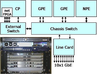
Hardware Components
The hardware components of our prototype SPP are shown at right. The system consists of a number of processing components that are connected by an Ethernet switching layer. From a developer's perspective, the most important components of the system are the Processing Engines that host the applications. The SPP includes two types of PEs. The General-Purpose Processing Engines (GPE) are conventional server blades running the standard PlanetLab operating system. The current GPEs are dual Xeons with a clock rate of xx, xx GB of DRAM and xx GB of on-board disk. The Network Processor Blades (NPE) include two IXP 2850s, each with 16 cores for processing packets and an xScale management processor. Each IXP has 750 MB of RDRAM plus four independent SRAM banks, and the two share an 18 Mb TCAM. The NPE also has a 10 GbE network connection and is capable of forwarding packets at 10 Gb/s.
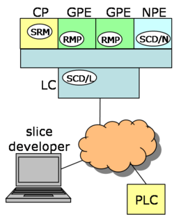
All input and output passes through a Line Card (LC) that has ten GbE interfaces. In a typical deployment, some of these interfaces will have public IP addresses and be accessible through the Internet, while others will be used for direct connection to other SPP nodes. The LC is implemented with a Network Processor blade and handles the routing of traffic between the external interfaces and the GPEs and NPEs. This is done by configuring filters and queues within the LC. The system is managed by a Control Processor (CP) that configures application slices based on slice descriptions obtained from PlanetLab Central, a centralized database that is used to manage the global PlanetLab infrastructure. The CP also hosts a netFPGA, allowing application developers to implement processing in configurable hardware, as well as software.
Our prototype system is shown in the photograph. We are using board level components that are compatible with the Advanced Telecommunication Computing Architecture (ATCA) standards. ATCA components include the server blades, the NP blades and the chassis switch, which actually includes both a 10 GbE switch and a 1 GbE control switch. The ATCA components are augmented with an external 1 GbE switch and a conventional rack-mount server that implements the CP.
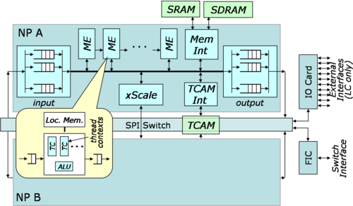
Network Processor blades are used for both the NPE and the LC. NPs are engineered for high performance on IO-intensive packet processing workloads. The dual Intel IXP 2850s used in the SPP's NP blades each contain 16 multi-threaded Micro-Engines (ME) that do the bulk o f the packet processing, plus several high bandwidth memory interfaces. In typical applications DRAM is used primarily for packet buffers, while SRAM is used for implementing lookup tables and linked list queues. There are also special-purpose on-chip memory resources, both within the MEs and shared across the MEs. An xScale Management Processor (MP) is provided for overall system control. The MP typically runs a general-purpose OS like Linux, and has direct access to all of system memory and direct control over the MEs.
As with any modern processor, the primary challenge to achieving high performance is coping with the large processor/memory latency gap. Retrieving data from off-chip memory can take 50-100 ns (or more), meaning that in the time it takes to retrieve a piece of data from memory, a processor can potentially execute over 100 instructions. The challenge for system designers is to try to ensure that the processor stays busy, in spite of this. Conventional processors cope with the memory latency gap primarily using caches. However for caches to be effective, applications must exhibit locality of reference, and unfortunately, networking applications typically exhibit limited locality of reference, with respect to their data.
Since caches are relatively ineffective for networking workloads, the IXP provides a different mechanism for coping with the memory latency gap, hardware multi-threading. Each of the MEs has eight separate sets of processor registers (including Program Counter), which form the MEs hardware thread contexts. An ME can switch from one context to another in 2 clock cycles, allowing it to stay busy doing useful work, even when several of its hardware threads are suspended, waiting for data to be retrieved from external memory. Multithreading can be used in a variety of ways, but there are some common usage patterns that are well-supported by hardware mechanisms. Perhaps the most commonly used (and simplest) such pattern involves a group of threads that operate in a round-robin fashion, using hardware signals to pass control explicitly from one thread to the next. Round robin processing ensures that data items are processed in order and works well when the variation in processing times from one item to the next is bounded (which is commonly the case in packet processing contexts), and is straightforward to implement.
Each ME has a relatively small dedicated program store, from which it executes instructions. This limits the number of different functions that can be implemented by a single ME, favoring programs that are divided into smaller pieces and organized as a pipeline. The MEs support such pipeline processing by providing dedicated FIFOs between consecutive pairs of MEs (Next Neighbor Rings). A pipelined program structure also makes it easy to use the processing power of the MEs effectively, since the parallel components of the system are largely decoupled from one another.
The two NPs on the card share a Ternary Content Addressable Memory (TCAM). The TCAM can be configured for key sizes ranging from 72 bits up to 576 bits. In the LC, it is used to implement general packet filters based on the standard IP 5-tuple (source+destination address, protocol, source+destination port). In the NPE, it is used to implement generic lookups with application-specific semantics. The two NPs communication through an onboard SPI switch to the backplane and an optional IO card, with ten 1 GbE interfaces. In the SPP, the LC uses an IO card, while the NPE does not.
Network Processor Datapath Software
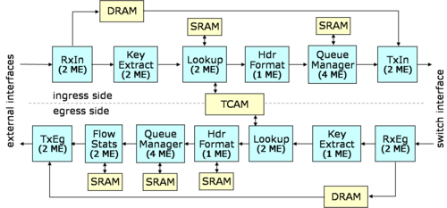
The software components use in the Line Card are shown at right. One of the two NPs on the LC is used to process incoming traffic (from the external interfaces to the chassis switch) and the other is used to process outgoing traffic. In both cases, the processing is structured as a pipeline in which packets flow from stage-to-stage thru inter-stage buffers (not shown). Most stages use more than one MicroEngine (ME), typically with the load being distributed in round robin fashion across the MEs and their individual thread contexts.
In the ingress pipeline, the RxIn block copies arriving packets from the IO interface into fixed size DRAM buffers (2KB each) and passes a pointer to the next stage in the pipeline. The Key Extract block reads fields from the packet header that are required to form a lookup key and passes these on to the next stage. The Lookup block formats the lookup key and issues queries to the external TCAM, which returns a pointer to results in an external SRAM. These results include modified values of selected header fields and a queue identifier. The lookup key includes the hardware interface on which the packet was received and the full IP header 5-tuple. Packets for which there is no configured filter are discarded and counted. The control software can avoid such discarding by including a default filter that directs any otherwise matched packets to the SPP's Control Processor. The lookup result includes the address of the hardware component which is to get the packet next and a queue identifier. The Header Format block rewrites selected fields in the header portion of the packet stored in DRAM. The Queue Manager block implements a general queueing subsystem. Each of the four MEs implements five independent packet schedulers. Each packet scheduler implements a Weighted Deficit Round Robin scheduling algorithm, and can be independently rate controlled, limiting its total output traffic. Each queue has a configurable weight that determines its share of its scheduler's output bandwidth, and a configurable discard threshold that limits the number of packets it can hold. The TxIn block, at the end of the pipeline, copies packets from their DRAM buffers to the output interface and returns buffers to the free list.
There are two additional MEs used in the ingress pipeline that are not shown. One manages the free space list, while the other implements statistics counters on behalf of the other blocks. We have also not shown the connections to/from the xScale. Arriving packets may be diverted to the xScale by the Lookup block and may be injected into the pipeline by the xScale at the Header Format block.
The egress pipeline is similar to the ingress pipeline, although some of the details differ. One major difference is that the egress pipeline includes a Flow Statistics block that keeps track of outgoing traffic on a per-flow basis. This is to allow it to support the PlanetLab requirement that all outgoing traffic be tracable back to the specific application slice that sent it. This allows PlanetLab staff to respond to complaints when slices send unwanted traffic to destination hosts on the Internet. Traffic statistics are compiled by the Flow Stats block (which is implemented by two MEs) and passed onto the xScale. It sends aggregated traffic records to the Control Processor, and these records are ultimately sent on to PlanetLab Central where they are archived.
The processing of packets by the Line Card is largely determined by TCAM filters. Many of these filters are installed in response to requests from SPP users. Filters can be created by users either explicitly or implicitly. Explicit configuration is used to configure a TCP or UDP port on an interface, and will be discussed further in a later section. Implicit configuration is done using Network Address Translation. The LC implements NAT for outgoing connections originating on the CP or GPEs. For example, if the LC receives an outgoing packet for a UDP connection for which there is no configured filter, it will forward the packet to the xScale and the NAT daemon running on the xScale will allocate a free source port number for the outgoing interface and install a filter in the TCAM so that subsequent packets belonging to that UDP connection will have their source port number's translated as they pass through the egress pipeline. A filter is also inserted into the ingress pipeline so that the reverse translation is performed on arriving packets belonging to the connection. NAT is also performed for TCP and ICMP packets, but it is not implemented for higher level applications that embed port numbers in their payloads. This means for example, that the SPP does not support outgoing FTP connections, although it can (and does) support SSH and SFTP. Also note that while port number translation is performed on both ingress and egress packets, only egress packets trigger the addition of a new filter pair.
The figure at right shows the current version of the software that runs on the NPE. This software uses just one of the two NPs on the blade and is structured similarly to the Line Card software. The most significant difference is that the NPE is designed to implement the fastpaths of different PlanetLab applications. Since different applications may have different header formats, the NPE supports multiple code options for handling different formats. Each slice selects a particular code option for its fast path processing, allowing multiple slices to use the same code option. Code options are implemented within the Parse and Header Format blocks, which precede and follow the Lookup block. The Parse block extracts the appropriate header fields and forms a 112 bit Lookup key which it passes on to the Lookup block. The Lookup block treats this as a generic bit string, which it uses to query the TCAM. The result returned by the TCAM is passed onto the Header format block which does whatever post-lookup processing is required, such as modifying fields in the outgoing packet headers. Each slice has its own set of filters in the TCAM (each filter includes a slice id as a hidden part of its lookup key, allowing the Lookup block to restrict lookups to the keys that are relevant for a particular packet), and has the freedom to define the semantics of the Lookup key and result in whatever way is appropriate to it. Software running in a GPE on behalf of a slice can insert filters into an NPE using a generic interface that treats the filter as an unstructured bit string. We generally expect slice developers to provide more structured interfaces that are semantically meaningful to their higher level software, and implement those interfaces using the lower level generic interface provided by the SPP.
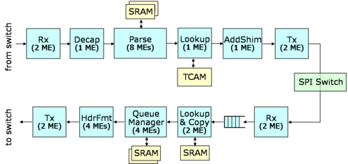
Our original intention had been to have each of the two NPs on the blade operate execute the software described above, running independently of the other. Unfortunately, the blade does not support bi-directional sharing of the switch interface by the two NPs, making it impossible to implement this approach. Consequently, we are planning a second version of the NPE software that distributes the processing tasks across the two NPs. This will give us an NPE capable of sustained throughputs up to 10 Gb/s. At the same time, we are making some additional improvements. The most significant of these is the addition of support for multicast.
As shown in the figure, the new NPE software will devote eight MEs to the parse block, substantially increasing the number of cycles available for application-specific packet processing. The results of the lookup produced in the first NP will be inserted into a shim header that will be propagated to the second NP. This will include a secondary lookup index which will be used in the second NP to access other information, such as the set of outgoing interfaces to which the packet should be forwarded. The Header Format block has been moved after the QM, allowing for the copies of multicast packets to be handled differently.
Control Software
Planned SPP Deployment
map of planned node locations
details of a typical site with connections to router and other sites
Using SPPs
Discuss how to define slices in myPLC, login to SPP nodes and do configuration. Keep the main flow at a high level, but add a page that gives a tutorial on how the GEC 4 demo is done.
